Electrodialysis Reversal (EDR)
Electrodialysis (ED) is an electrically driven membrane process used to demineralize brackish water. Water is classified as brackish when mineral content ranges between that of fresh drinking water and that of seawater. Brackish water contains more than 500 mg/L of total dissolved solids (TDS) and seawater more than 30,000 mg/L TDS.
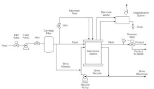
ED and electrodialysis reversal (EDR) reduce TDS in brackish source water by electrically removing contaminants that exceed acceptable levels for drinking and process water. The ED and EDR processes are competitive with reverse osmosis (RO) in treating brackish waters. Typical ED systems include chemical feed systems for antiscalant and perhaps acid addition, a cartridge filter for prefiltration, the ED unit, and equipment for aeration, disinfection, and stabilization. EDR systems can often operate without fouling and scaling chemical feed, and they can treat high-fouling sources more efficiently than RO.
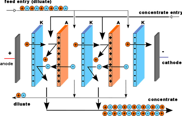
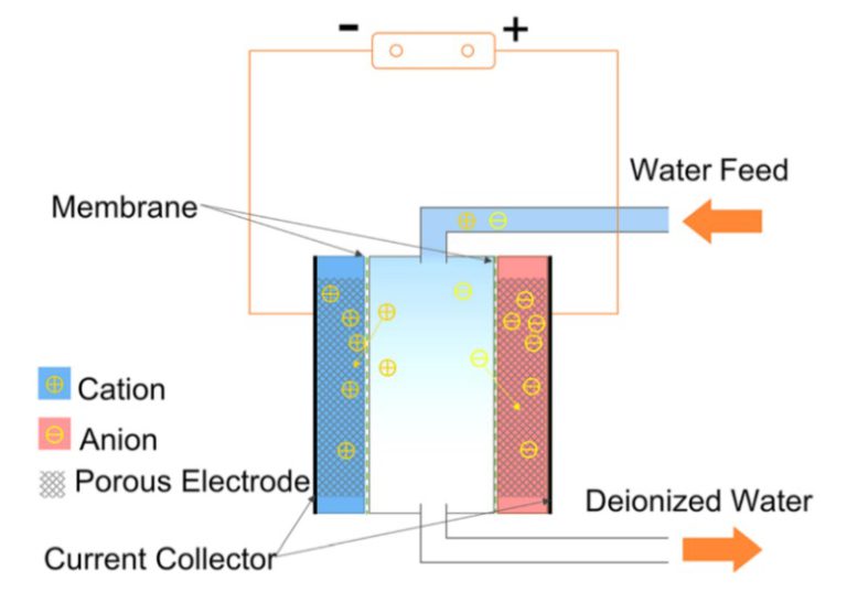
Electrodialysis is an electrochemical separation process in which ions are transferred through ion exchange membranes by means of a DC voltage. ED selectively removes dissolved solids, based on their electrical charge, by transferring the brackish water ions through a semipermeable ion exchange membrane charged with an electrical potential. Figure above shows a schematic of an entire ED system. It points out that the feedwater becomes separated into the following three types of water: (1) product water, which has an acceptably low TDS level; (2) brine, or concentrate, which is the water that receives the brackish water ions; and (3) electrode feedwater, which is the water that passes directly over the electrodes that create the electrical potential.
EDR involves reversing the electrical charge to a membrane after a specific interval of time. As described later, this polarity reversal helps prevent the formation of scale on the membranes. Figure 1-6 shows a schematic of an EDR system. The setup is very similar to an ED system except for the presence of reversal valves.
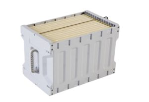
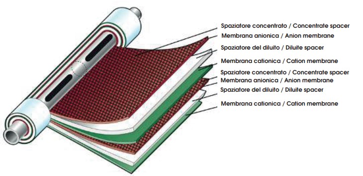
Membrane stacks
All ED and EDR systems are designed specifically for a particular application. The amount of salt to be removed is determined by the configuration of the membrane stack. This section describes physical components of the membrane stack, which is the fundamental working unit of an ED or EDR system.
Spaces between membranes represent flow paths formed by polyethylene spacers. The dimensions of large spacers range from 18 in. × 40 in. (0.5 m × 1 m) to 3.3 ft × 6.5 ft (1 m × 2 m). Spacers may carry either demineralized or concentrated water because they are arranged in the stack so that the demineralized streams and the concentrate streams flow into separate single manifolds. In a typical system, each stack removes from 30 to 60 percent total dissolved solids (TDS) at flow rates of 6 to 8 L/s and pressures of 3.5 Bar.
Cell pairs form the basic building blocks of an EDR membrane stack consists of the following:
- anion permeable membrane
- concentrate spacer
- cation permeable membrane
- dilute stream spacer
Cation membrane. The cation membrane is a sheet in which a cation exchange resin is embedded. This membrane allows the passage of cations while blocking the passage of water and anions. Negatively charged resin repels the negative ions while allowing the positive ions to pass through the membrane. As feedwater travels along the membrane, positively charged sodium ions (mobile counter cations) are attracted toward the negatively charged fixed anion sites. Sodium ions are transported through the membrane supported by the polymer support structure and into the concentrate stream.
Anion membrane. The anion membrane is similar in structure to the cation membrane except that the resin embedded onto the sheet is an anion exchange resin. This membrane allows passage of anions while blocking passage of both cations and water. The active site on an anion membrane is quaternary ammonia, which repels positively charged ions and allows negatively charged ions to pass through the membrane.
Electrocoagulation (EC)
Electrocoagulation is an electrochemical water treatment process that removes contaminants through the coagulation and precipitation of impurities from water or wastewater. This method is commonly used to treat industrial effluents, sewage, and contaminated water sources.
Here’s a brief overview of the electrocoagulation process:
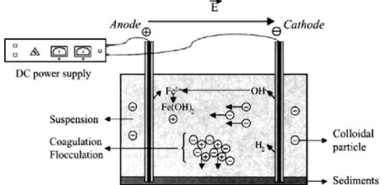
- Electrode Configuration: Electrocoagulation systems consist of one or more pairs of metal electrodes (usually aluminum or iron) submerged in the water to be treated. These electrodes are connected to a power source.
- Generation of Electrolysis: When an electric current is applied, it causes the anode (positive electrode) to release metal ions (e.g., aluminum or iron cations) into the water, and the cathode (negative electrode) generates hydroxide ions (OH-) by reducing water molecules.
- Coagulation: The metal cations and hydroxide ions form metal hydroxide complexes in the water, creating flocs or precipitates. These flocs attract and encapsulate contaminants such as suspended solids, colloids, organic matter, and certain ions through charge neutralization and adsorption.
- Contaminant Removal: The generated flocs increase in size and weight, causing them to settle or float to the surface for easy separation. The contaminants are physically removed or can be further treated by sedimentation, flotation, or filtration.
- pH Adjustment: In some cases, pH adjustment may be necessary to optimize the coagulation process since the pH can influence the effectiveness of coagulation and precipitation.
- System Monitoring: Monitoring the electrical current, water quality, and other parameters is essential to ensure the efficiency of the electrocoagulation system.
- Advantages: Electrocoagulation offers several advantages, including the ability to remove a wide range of contaminants, ease of operation, reduced chemical usage, and the potential for metal recovery.
- Limitations: This method may not be suitable for all water treatment applications, and its efficiency can be influenced by factors like water chemistry and electrode material.
In summary, electrocoagulation is an electrochemical process that utilizes metal ions and hydroxide ions generated by electrodes to coagulate and remove contaminants from water, making it a valuable method for water and wastewater treatment in various industrial and environmental settings.
Capacitive deionization (CDI)
Capacitive deionization (CDI) is a water treatment process that removes ions from water using electrostatic attraction and adsorption. It’s a sustainable and energy-efficient method for desalination and purification.
Here’s a brief overview of the CDI process:
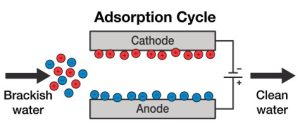
- Electrodes and Electrolyte: A typical CDI setup consists of two porous electrodes (often made of activated carbon) immersed in an electrolyte solution. These electrodes are placed parallel to each other, and the water to be treated flows between them.
- Charging Phase: When a voltage is applied across the two electrodes, it creates an electric field between them. Ions in the water are attracted to the oppositely charged electrodes. Positive ions (cations) move towards the negatively charged electrode, and negative ions (anions) move towards the positively charged electrode.
- Ion Adsorption: As the ions approach the electrodes, they are electrostatically adsorbed onto the electrode surfaces. This adsorption process effectively removes the ions from the water, leaving behind purified water in between the electrodes.
- Storage of Ions: The adsorbed ions accumulate on the electrode surfaces. They can be stored until the electrodes are saturated or until the system needs to be regenerated.
- Discharging Phase: When the electrodes are saturated with ions or when it’s time to release the stored ions, the voltage is reversed or reduced. This causes the ions to desorb from the electrode surfaces and return to the water. This regeneration step restores the electrodes for the next cycle.
- Collection of Purified Water: The water between the electrodes, having lost its ions during the charging phase, is now purified and can be collected as treated water. The efficiency of ion removal depends on factors like electrode material, surface area, and the applied voltage.
CDI is an eco-friendly desalination and water purification technology because it doesn’t rely on harmful chemicals, and it can be powered by renewable energy sources. It’s particularly promising for applications where energy efficiency and sustainability are essential.
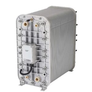
Electrodeionization (EDI)
Electrodeionization (EDI) is a water purification process that combines ion exchange resins with an electric field to remove ions and impurities from water. It’s widely used in industries like pharmaceuticals, electronics, and power generation.
Here’s a brief overview of the process:
- Ion Exchange Resins: Water first passes through ion exchange resin beds. These resins contain positively charged cations and negatively charged anions, which attract and bind to ions in the water.
- Electric Field: An electric field is applied across the resin beds using electrodes. This electric field helps to pull the ions away from the resin and into the surrounding water.
- Ion Migration: Positive ions (cations) migrate towards the negatively charged electrode (cathode), while negative ions (anions) move towards the positively charged electrode (anode).
- Deionization: As the ions migrate, they are effectively stripped from the water and collect at the respective electrodes. This process continuously regenerates the ion exchange resins.
- Separation: The removed ions at the electrodes can be periodically flushed out, ensuring that the ion exchange resins remain effective.
- Pure Water Output: What remains is purified water with greatly reduced ion and impurity content.
- Continuous Process: EDI is a continuous and chemical-free process, unlike traditional ion exchange, which requires periodic regeneration with chemicals. The resulting purified water is of high quality and meets stringent industry standards. EDI is environmentally friendly, efficient, and often used as a final polishing step in ultrapure water production.
Reverse Osmosis (RO)
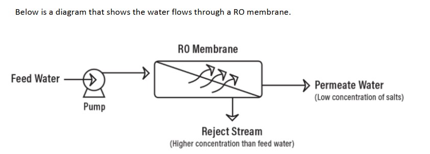
Reverse osmosis, commonly referred to as RO, is a process where you remove a large portion of dissolved solids and other contaminants from water by forcing the water through a semi-permeable reverse osmosis membrane. Osmosis is a naturally occurring phenomenon and one of the most important processes in nature. It is a process where a weaker saline solution will tend to migrate to a strong saline solution.
Reverse osmosis works by using a high-pressure pump to increase the pressure on the salt side of the RO and force the water across the semi-permeable RO membrane, leaving almost all (around 95% to 99%) of dissolved salts behind in the reject stream. The amount of pressure required depends on the salt concentration of the feed water. The more concentrated the feed water, the more pressure is required to overcome the osmotic pressure.
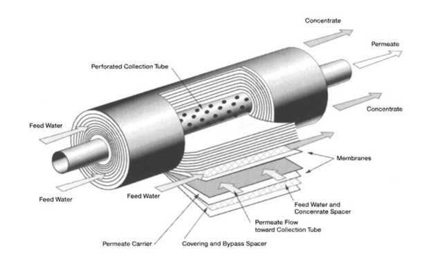
In very simple terms, feed water is pumped into a Reverse Osmosis (RO) system and you end up with two types of water coming out of the RO system: good water and bad water. The good water that comes out of an RO system has most contaminants removed and is called permeate. Another term for permeate water is product water. Permeate is the water that was pushed through the RO membrane and contains very little contaminants. RO system sizes are based on permeate flow. A 100 gpm RO system implies that the RO system will produce 100 gpm of permeate water. The ‘bad’ water is the water that contains all the contaminants that were unable to pass through the RO membrane and is known as the concentrate, reject, or brine. All three terms (concentrate, reject, and brine) are used interchangeably and mean the same thing. The following has a simple schematic that shows water flows through an RO system.
Reverse Osmosis can remove 95-99% of the dissolved salts (ions), particles, colloids, organics, bacteria, and pyrogens from the feed water. An RO membrane rejects contaminants based on their size and charge. Any contaminant that has a molecular weight greater than 200 is likely rejected by a properly running RO system. Likewise, the greater the ionic charge of the contaminant, the more likely it will be unable to pass through the RO membrane.
It is important to understand that an RO system employs cross filtration rather than standard dead-end filtration where the contaminants are collected within the filter media. With cross filtration, the solution passes through the filter, or crosses the filter, with two outlets: the filtered water goes one way, and the contaminated water goes a different route. To avoid a buildup of contaminants, cross flow filtration allows water to sweep away contaminant build up and allow enough turbulence to keep the membrane surface clean.
There are a handful of calculations that are used to judge the performance of an RO system and for design considerations. An RO system has instrumentation that displays quality, flow, pressure and sometimes other data like temperature or hours of operation. Proper pretreatment using both mechanical and chemical treatments is critical for an RO system to prevent fouling, scaling and costly premature RO membrane failure and frequent cleaning requirements.
The Reverse Osmosis systems produced by Payam Avaran Nano fanavary Fardanger are available for sale in capacities of 10, 25, and 50 cubic meters per day, featuring the following specifications:
1- Equipped with all stainless steel pumps
2- Entirely constructed from SS electrical materials
3- Integrated with PLC and HMI for enhanced performance
4- Two dosing pumps for chemical injection
5- Equipped with an automatic CIP (Clean-in-Place) system for membrane cleaning
6- Input TDS conductivity: <3000ppm
These systems are designed to provide efficient and reliable water treatment solutions for clients around the globe.
Nano adsorbents
Nano adsorbents are nanoscale materials designed to adsorb or capture various substances from their surroundings. They exhibit unique properties due to their small size and high surface area, making them highly effective in numerous applications. Here’s a brief explanation of nano adsorbents:
Introduction: Nano adsorbents are engineered materials with particle sizes in the nanometer range (typically less than 100 nanometers). Their small size grants them exceptional surface area-to-volume ratios, resulting in enhanced reactivity and adsorption capabilities.
Key Characteristics:
- High Surface Area: Nano adsorbents possess a significantly greater surface area compared to their bulk counterparts, allowing for increased contact with target substances.
- Tailored Properties: Their properties can be customized by altering the nanomaterial’s composition, size, and surface chemistry to suit specific adsorption needs.
- Rapid Adsorption: Nano adsorbents offer fast adsorption kinetics, which is crucial in applications like water purification and gas capture.
- Versatility: They can adsorb a wide range of substances, including pollutants, heavy metals, organic molecules, and gases.
In summary, nano adsorbents are cutting-edge materials with immense potential to address pollution and purification challenges across various industries. Their unique properties make them a valuable tool for a cleaner and healthier environment.
Cavizone
The combination of cavitation and ozonation is a powerful water treatment process that effectively removes contaminants and purifies water. Here’s a brief overview of this process:
Combination of Cavitation and Ozonation:
– Cavitation: Cavitation is a phenomenon where bubbles of gas form and collapse in a liquid due to a decrease in pressure. This implosion of bubbles generates intense localized energy and shock waves, leading to the fragmentation and disintegration of contaminants present in the liquid. Cavitation is typically achieved through devices like ultrasonic generators or hydrodynamic cavitation reactors.
– Ozonation: Ozonation involves the introduction of ozone (O3), a highly reactive and powerful oxidizing gas, into the water. Ozone breaks down organic and inorganic pollutants by oxidizing them, effectively removing impurities, pathogens, and odors from the water. It is widely used in water and wastewater treatment processes.
The combination of cavitation and ozonation is a synergetic approach that enhances the water treatment process. Cavitation generates microbubbles and turbulence in the water, significantly increasing the surface area for ozone contact with contaminants. This, in turn, accelerates the ozonation process and improves its efficiency in breaking down pollutants.
The key advantages of this combined approach include:
- Enhanced Oxidation: The mechanical effects of cavitation assist in the dispersion of ozone and improve its contact with pollutants, leading to faster and more thorough oxidation.
- Effective Disintegration: Cavitation-induced shock waves help in breaking down larger particles or organic matter into smaller, more susceptible fragments for ozonation.
- Improved Pathogen Removal: The combination can be highly effective in eliminating bacteria, viruses, and other microorganisms from water.
- Reduced Ozone Consumption: The synergistic effects reduce the amount of ozone required for water treatment, making the process more cost-effective.
In summary, the combination of cavitation and ozonation is a cutting-edge water treatment technique that leverages the mechanical forces of cavitation to enhance the oxidative power of ozone. This synergistic approach efficiently removes contaminants, making it a valuable method for water purification and wastewater treatment.
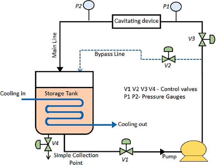
Hydrodynamic Cavitation
Hydrodynamic cavitation is a phenomenon that occurs when a liquid flows through a constricted passage at high velocities, causing a significant drop in pressure. This drop in pressure leads to the formation and subsequent collapse of small vapor-filled cavities or bubbles within the liquid.
The process can be summarized in the following steps:
- Constriction: A liquid is forced through a narrow passage, such as a Venturi tube or an orifice. This constriction accelerates the flow of the liquid, increasing its velocity.
- Pressure Drop: As the liquid flows through the constriction, the velocity increases, while the pressure decreases due to Bernoulli’s principle. This pressure drop is critical for initiating cavitation.
- Bubble Formation: The reduced pressure in the liquid causes tiny vapor-filled bubbles or cavities to nucleate within the liquid. These bubbles are often referred to as “cavitation bubbles.”
- Growth and Collapse: The cavitation bubbles continue to grow as the liquid flows through the low-pressure region. Once the bubbles reach a critical size, they rapidly collapse due to the surrounding higher-pressure environment. This collapse is an implosive event, creating shockwaves and intense local heating.
- Effects: The collapse of cavitation bubbles can produce various effects, such as high temperatures, intense turbulence, and shockwaves. These effects can be harnessed for various applications, including wastewater treatment, emulsification, and the enhancement of chemical reactions.
It’s important to note that hydrodynamic cavitation has both beneficial and detrimental effects depending on the application. While it can be used for mixing and enhancing certain chemical processes, it can also cause erosion and damage to equipment due to the violent nature of bubble collapse. Proper engineering and control are essential to optimize its use in specific scenarios.
Ultrafiltration (UF)
Ultrafiltration is a separation process that’s used in various industries, including water purification and biotechnology. It operates on the principle of size-based filtration.
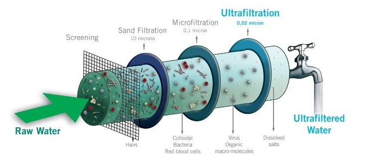
Here’s a brief explanation of the process:
- Purpose: Ultrafiltration is employed to separate particles and molecules based on their size, allowing smaller substances to pass through a semi-permeable membrane while retaining larger ones.
- Semi-Permeable Membrane: A critical component is the semi-permeable membrane, which has tiny pores that allow only certain-sized particles to pass. The size of the pores can be adjusted depending on the desired separation.
- Pressure: A driving force, typically hydraulic pressure, is applied to the fluid mixture that needs to be separated. This pressure pushes the mixture against the membrane.
- Separation: The pressure forces smaller molecules (solvent and solutes) to pass through the membrane, while larger particles (proteins, colloids, or impurities) are retained on one side of the membrane.
- Permeate and Retentate: The smaller molecules that pass through the membrane are called the “permeate,” while the larger ones that are held back are the “retentate.”
- Applications: Ultrafiltration is used in various applications, such as purifying water by removing contaminants, concentrating proteins and enzymes in biotechnology, and treating wastewater in industrial processes.
7. Maintenance: Periodic maintenance, including cleaning or replacing the membrane, is essential to ensure the efficiency of the ultrafiltration system.
In summary, ultrafiltration is a filtration process that separates substances based on their size by using a semi-permeable membrane and pressure, making it valuable in a wide range of industries.